Power Supplies with Enhanced Peak Power Capability
April 21, 2020 by Aaron Yarnell - 8 Minute Read
One of the common characterization parameters for electronic power supplies is the maximum power they are able to provide to a load. Most designers select a power supply such that the nominal load is in the range of 60% to 80% of the maximum power rating of the supply. This can also be thought of as the maximum capacity of the power supply is 25% to 67% greater than the nominal load. In making this design decision the engineer is allowing for the system to operate with peak load conditions that are within the specified performance range of the power supply. However, there are some classes of power supply loads which do not fit this operating model:
- Loads with periodic high levels that otherwise operate at extremely low power levels.
- Loads with large start-up power requirements that then settle into lower operating power levels.
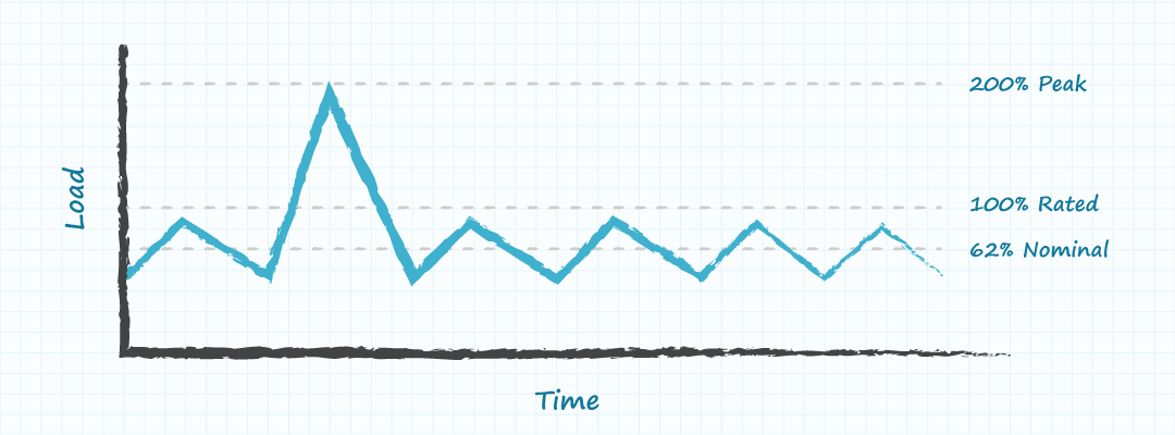
Design engineers often ask their suppliers “Are power supplies available that have a high peak power rating that can be used to address large transient loads?” CUI’s power supplies with Power Boost address this requirement. These products have output power specifications similar to traditional power supplies but have the added ability to support a peak power level that is double the maximum rated level (for a duration of up to ten seconds and with a maximum duty cycle of 10%). This allows customers to select a power supply based upon the nominal power level and not the peak power requirements.
In making this selection the designer is able to use a power supply with a lower maximum power rating and potentially reduce the cost of the system. In this blog post we will be discussing constant voltage power supplies and thus the concept of output current can be used interchangeably with that of output power (the output current is proportional to the output power).
Current Limiting in Conventional Power Supply Designs
Most power supplies are designed with output over-current detection and protection. The internal over-current detection circuit is designed to react within milliseconds in order to protect the power supply from damage in the event of excessive load currents. Although the power supply may not meet the datasheet operating specifications when the load current is greater than the specified maximum operating current, the supply must still be designed such that the operation during an over-current event does not damage the supply. Placing the over-current limit close to the maximum operating current means that the supply will not be allowed to continue to operate with much greater output current (and internal power dissipation) before the over-current protection activates. Typically the over-current threshold is set as close as possible to the maximum rated output current (often 110% of maximum output current) to enable a cost efficient supply.
The power supply philosophy of operating at a nominal output current of about 62% of the maximum specified load current and setting the over-current protection threshold at 110% of the maximum specified load current works well for loads where the ratio of peak load to average load (crest factor) is about 1.8 or less (110%/62%). For loads with a crest factor of greater than 1.8 (greater peak loads) the cost of the power supply relative to the average power drawn can be unacceptable due to the need to operate the supply at nominal load that is considerably less than the maximum load rating. In systems that have loads with crest factors greater than 1.8 it is advantageous for reasons of cost and size to have a power supply that is designed with a high over-current tolerance.
Examples of High Crest Factor Loads
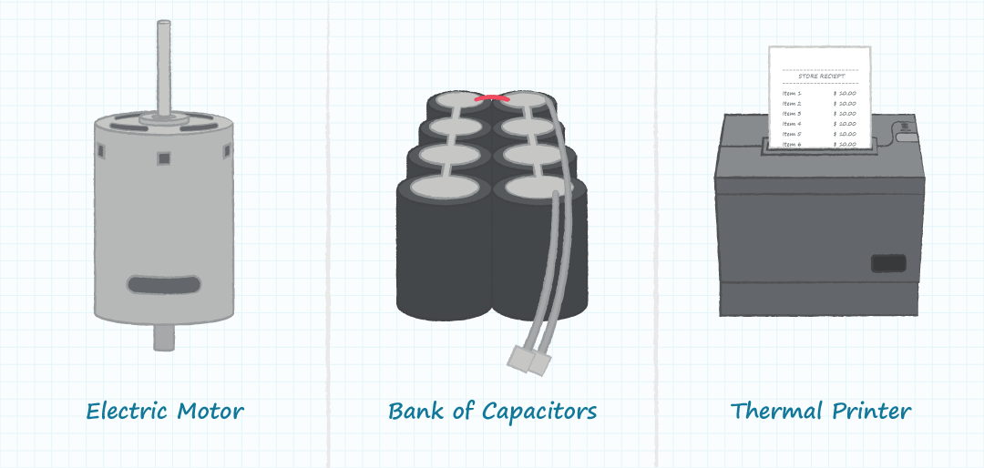
There are many types of power supply loads which draw a large amount of power for a short duration and then settle into a lower power mode, such that the crest factor may be 3:1 or greater. Some examples of products and applications with such characteristics include:
- Thermal printers which have heating elements that are over-driven initially in order to quickly achieve the proper operating temperature.
- Electric motors at start-up when the current draw is high due to the absence of back-EMF.
- Large banks of filter capacitors which draw high current when initially charged.
- Test modules that might perform a periodic and short duration test with high power consumption during the test event and low power consumption between test events.
Power Supply Components Critical for High Crest Factor Power Delivery
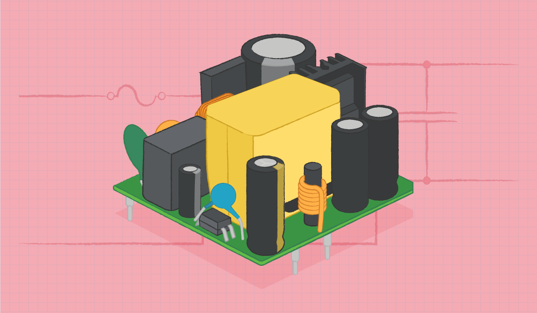
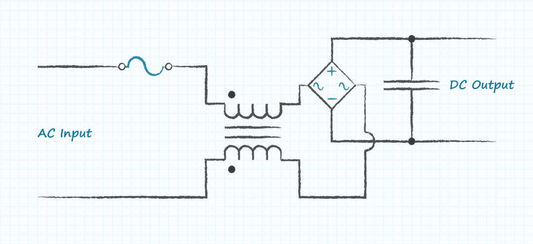
There are a few sections of the power supply which must be addressed in order to produce a cost-effective design that will support loads with high power crest factors. With most ac-dc power supplies the input current first flows through a fuse and EMI filter and then through a bridge rectifier where the input current charges a bulk capacitor (Figure 3). The bulk capacitor ensures that the rectified voltage feeding the remainder of the supply is maintained above a minimum level to enable the power supply circuits to operate properly. This capacitor must be of adequate size to support the maximum specified load current at the minimum specified input voltage. In the case of a CUI Power Boost supply the connection nodes of the bulk capacitor are made accessible to the user so that additional bulk capacitance can be added if it is required for the application.
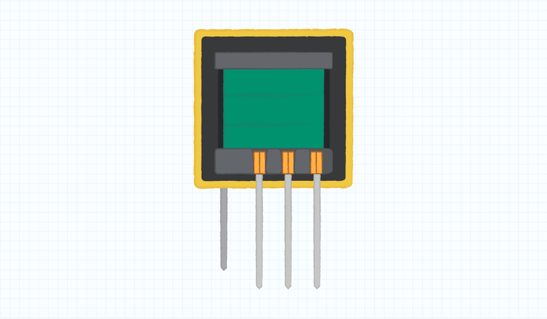
A second component in ac-dc power supplies with specific requirements for a Power Boost application is the isolation transformer or coupled inductor (Figure 4). This magnetic element needs to be designed so that it does not saturate during the delivery of the peak load current. Of additional concern is that the thermal dissipation capacity of this element must be great enough to handle the high peak load requirements.
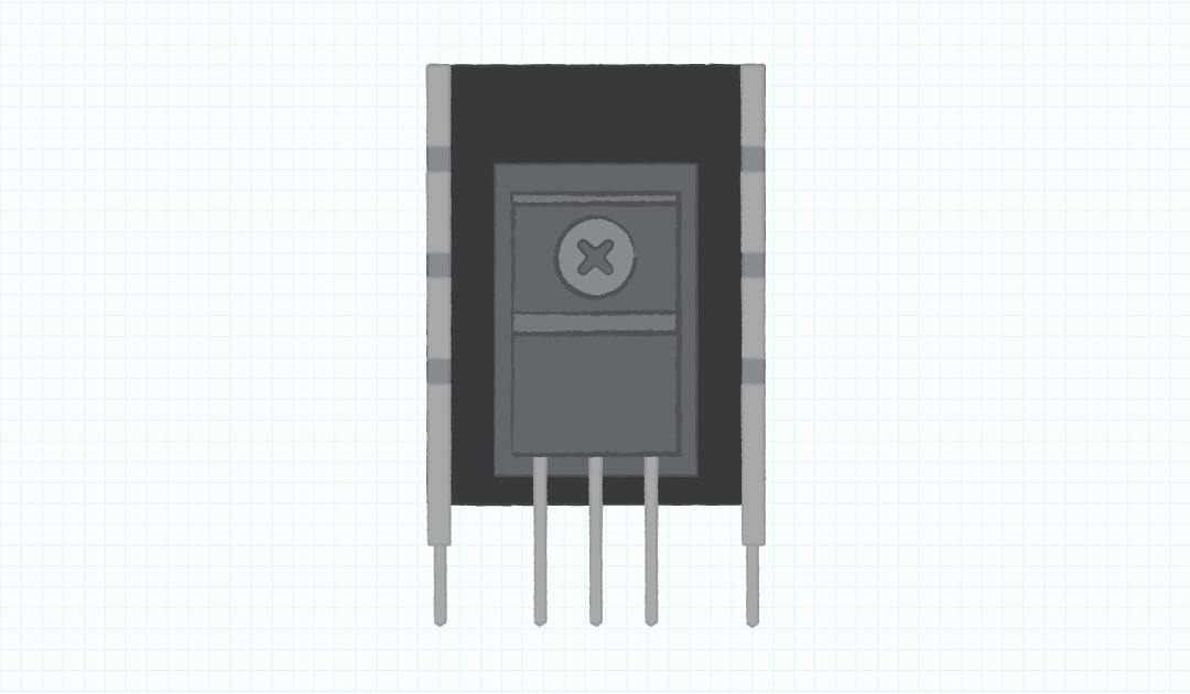
The primary side switch is a third element of a Power Boost supply that needs to be selected with characteristics to operate properly during the large peak load currents (Figure 5). In the case of the switch, the primary concern will be the power dissipation capability during the sustained peak load current. A possible solution to address this concern is to add thermal mass to the switch package to absorb the excessive heat generated during the peak load period. The thermal mass can be implemented either as an intrinsic characteristic of the package or as an external heat sink attached to the switch package.
Conclusion
While most loads for electronic power supplies have peak power requirements reasonably close to the nominal power levels, there are many applications which require a peak power level substantially greater than the nominal power level. For those applications in which there is a large but short duration and low duty cycle load spike, CUI’s Power Boost models are a great solution. This class of power supply delivers the required peak power in a smaller, lighter, and lower cost solution than would be available from conventional power supplies.
You May Also Like
Have comments regarding this post or topics that you would like to see us cover in the future?
Send us an email at powerblog@cui.com
