Selecting Appropriate Input and Output Plugs for Your Power Adapter
December 22, 2020 by Bruce Rose - 11 Minute Read

Power supplies have both input and output voltages and thus often have associated input and output connectors. The broad range of connectors available for input and output power transfer could not be reasonably covered in a single document. This discussion will instead focus on single phase ac-dc wall plug and desktop power supplies with ac wall plugs (input) and dc power connectors (output). Ac wall power connectors are standardized as are the associated voltages and maximum currents, thus the discussion regarding those connectors is greatly simplified. Dc output connectors are much less standardized and thus only a commonly available subset of the connectors will be discussed.
Ac Wall Plugs and Cords
Ac wall plug selection is typically straight forward and comes down to two criteria 1) in what regions and/or countries is the power supply intended to be used 2) does the application require two conductors or three conductors. Most countries have well defined plug and socket combinations, voltages, and frequencies. Since wall plug voltages are standardized, the ac power connectors are similarly rated to provide sufficient insulation for the standard voltages. The maximum current rating for the connectors is also standardized, with different ratings often employing physically different connector contacts such that mis-matched plug and socket combinations cannot be engaged.
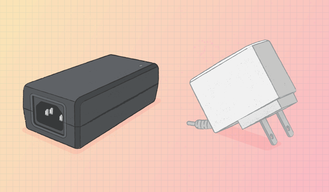
For desktop adapters the ac connection is a cord whereas a wall plug adapter will have an integrated plug. Many products with ac power cords have a standard ac inlet at the product chassis into which the power cord is connected. With these products it is possible to connect to different styles of wall sockets (in different regions or countries) by changing the ac power cord to one with the appropriate wall plug configuration. Some wall mount power adapters have a similar feature but instead of changing the ac power cord, the ac blades are interchangeable to accommodate different regions or countries.
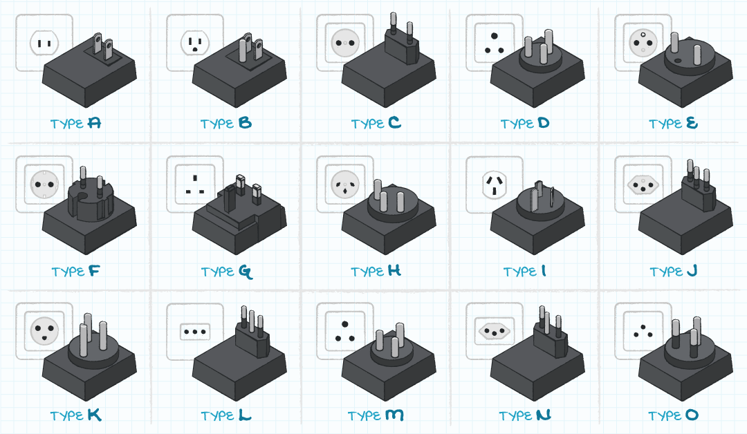
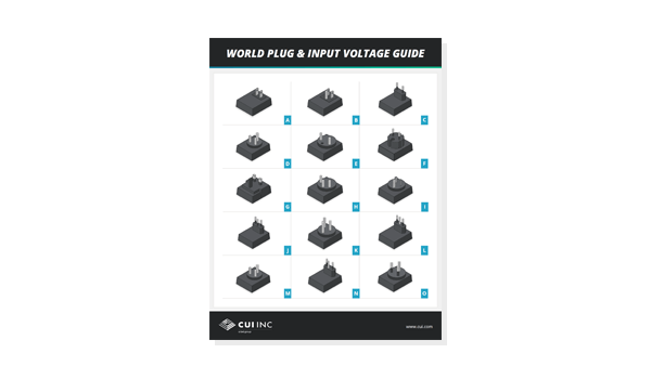
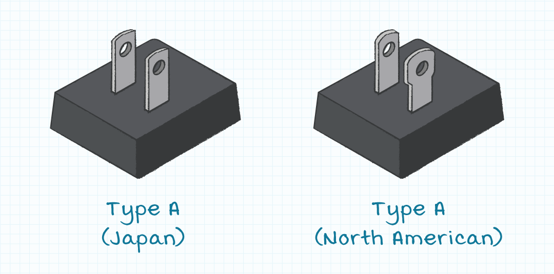
The International Electrotechnical Commission (IEC) publishes a guide that generally categorizes plugs with letter designations. While this guide does a good job of generically grouping plug types it does not account for all the possible nuances and variations. For example, plug Type A (used in North America, Central America, and Japan) is commonly polarized (neutral blade is wider) in North America however this is not always the case in Japan. Meaning Japanese plugs will typically work in North America but not always the other way around. Checkout our World Plug and Input Voltage Guide for info on international plug types.
Two Conductor Versus Three Conductor
In most of the international markets, single phase ac power has been standardized to be delivered with three conductors, although not all three conductors are employed in all applications. The three conductors consist of two power carrying conductors and a third Protective Earth (PE), Frame Ground (FG) or safety ground conductor. Power delivery is accomplished with the two power carrying conductors and the ground conductor is present for increased safety from dangerous voltages.
Modern power supply designs which utilize a two-conductor plug are constructed with sufficient insulation to ensure the safety of the design without requiring the ground conductor. CUI articles describing Insulation, Isolation, and Working Voltage and What's the Difference Between Class 2 and Class II Power Supplies provide additional information on this topic.
Line and Neutral Versus Line 1 and Line 2
In many single-phase ac power applications, the power carrying conductors are labeled as either Line and Neutral or as Line 1 and Line 2. The voltage potential of the Neutral conductor is intended to be close to that of the local ground and thus it is sometimes viewed as “safer” than the Line voltage. As was mentioned earlier in this discussion, the North American type A power plug employs a wider spade for the neutral conductor and a narrower spade for the line conductor. Matching slots in the North American wall socket ensure the line and neutral conductors can be identified at the load. It should be noted that many ac power plugs and sockets (other than the North American type A version) can be connected with the Line and Neutral conductors reversed (for example, the previously describe Japanese type A connector) and thus most loads for international markets do not differentiate between the Line and the Neutral ac input conductors.
When Line 1 and Line 2 conductors are employed the voltages of the two conductors are often balanced relative to the ground potential. A Neutral conductor is not employed when power is transferred with Line 1 and Line 2 conductors.
Dc Power Connectors
There are many standards for dc connectors and perhaps even more versions of non-standard connectors. The standard connectors we will discuss are barrel connectors, DIN connectors, and USB connectors.
Some of the features associated with the three categories of dc output power connectors are listed below:
| Barrel Connectors | DIN Connectors | USB Connectors |
|---|---|---|
| Standardized | Standardized | Standardized |
| Inexpensive | Higher current capability | Compact |
| No orientation required | Durable | Signal transmission |
Barrel Connectors
Barrel connectors are perhaps the most common design for dc power connectors because they are inexpensive to manufacture due to loose mechanical tolerances and have no required orientation when plugging them together.
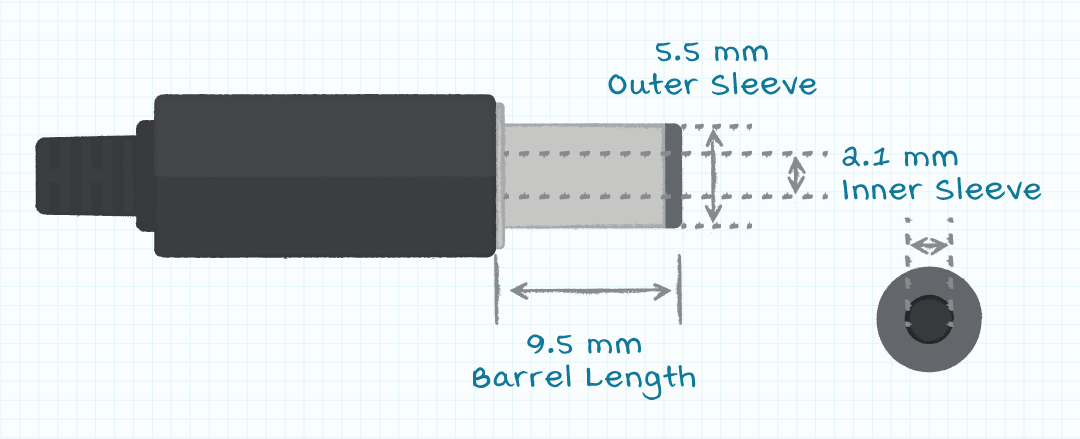
The most common form of barrel connectors has plugs constructed with concentric metal sleeves (barrels) separated by an insulator. Many standard diameters are available for both the inner and the outer sleeves and the length of the plug barrel. Common combinations of the diameters and length exist, but the design engineer will still need to specify the desired dimensions for the plugs used in their products.
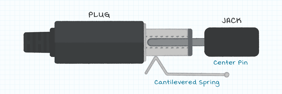
The corresponding barrel jack has a pin, which fits into the inner sleeve of the plug, often with a loose mechanical clearance and a cantilevered spring which contacts the outer sleeve of the plug. Like the barrel plug, the barrel jack will have dimensions for the central pin diameter, the inner case diameter, and the plug insertion depth.

When the barrel plug is inserted into the jack the spring in the jack pushes against the outer sleeve of the plug and forces the central pin on the jack to contact the inner sleeve of the plug. The selection of plug and jack dimensions needs to ensure the desired mechanical fit is achieved and the proper electrical connections are established.
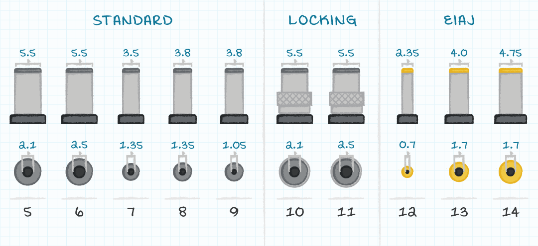
Although the features of the barrel connector make them appropriate for many applications, there are also some issues caused by the design of barrel connectors. The mechanical tolerance between the central pin on the jack and the inner sleeve on the plug is not standardized. Similarly, the force with which the cantilevered spring in the jack pushes against the outer sleeve of the plug is not standardized. This lack of standardizations means that the insertion and retention forces between the plug and the jack are difficult to specify and vary over a wide range. In standard barrel connectors there is no mechanical retention mechanism for the connection and thus the connection can accidently come apart. A solution to ensure the connection is retained is to use locking barrel connectors. Locking barrel connectors are available with either threaded or twist locking features.

The current rating of barrel connectors is determined by the force and surface area between the cantilevered spring and the outer sleeve and between the inner pin and the inner sleeve. The light forces and small surface areas limit the current ratings of the connectors.
Barrel connectors are available in a range of both inner and outer conductor diameters. Although there are no standards for the combinations of inner and outer diameters, product designers may choose to specify dimensions to either match existing products or to be unique from other products. The two most common barrel connector sizes are 5.5 mm outer sleeve diameter with 2.1 mm inner sleeve diameter and 5.5 mm outer sleeve diameter with 2.5 mm inner sleeve diameter.
Convention has evolved with the outer conductor as the ground or negative voltage and the inner conductor as the positive voltage. The advantage of this configuration is if the outer plug of the sleeve touches an exposed conductor then the exposed conductor will be connected to ground rather than to any other electrical potential. This convention is not always followed, and some product design teams place the positive potential on the outer conductor and the negative potential on the inner conductor.

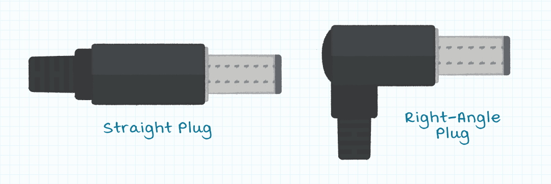
Selecting the power cord to be in-line with the power connector is the most common configuration used in the industry. This configuration is easy to manufacture and makes it more convenient for the user to align the connector when mating. However, there are applications where a right-angle plug configuration may be preferred. One reason for selecting a right-angle plug may be to allow the dc power cable to remain closer to the chassis as it feeds into the plug and thus allowing the physical footprint of the product to be smaller. Another reason for selecting a right-angle plug is to provide for retention between the two halves of the barrel connection. Because the power cord is at right angles to the connector, a force putting tension on the cord will force a torque on the barrel connector which will make it more difficult to disengage the connector. It is also possible to secure the cord under a hook or latch on the product case such that none of the tension force on the cable is transferred to the plug.
DIN Connectors
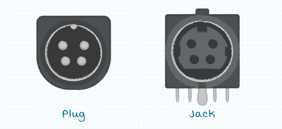
DIN power connectors are a style of connectors with four pin or socket contacts encased in a circular housing. These connectors were originally defined by a German standards organization (Deutsches Institut fur Normung), and thus the name of DIN connectors but are now defined by IEC 60130-9. Power DIN connectors are often used in moderate power applications when barrel connectors are not able to carry the required current. Confusion often exists between power DIN connectors and signal DIN connectors. There is not an absolute definition of a power DIN connector, but by convention power DIN connectors have four contacts spaced at approximately 90 degrees around the center of the connector. Although the dimensions of the pins and connectors are difficult to find in documentation, it can be assumed 4-pin DIN power plugs and jacks connect properly. Power DIN connectors can also be found with a threaded locking feature, like the barrel connectors.
USB Connectors
USB connectors were originally developed to deliver dc power and digital signals. The wide acceptance of the USB power voltage level and connectors has also made them popular for power only applications. The Type-A connector is perhaps the most popular USB connector at the present time and can be found in applications requiring 5 Vdc with load current levels of less than about 2 A. Variations of the USB Type-A connector (mini, micro, etc.) are also used in similar power delivery applications. One limitation of the Type-A connector and the variants is there is only one orientation of the connectors in which they will properly connect. This limitation requires the user to determine the correct orientation of the plug and jack either by visual identification or by attempted insertions.
The USB Type-C connector is more compact and can be inserted in either of two obvious orientations. The Type-C connectors can pass higher power levels than previous versions of the USB connectors and are rated to deliver a maximum of 20 V at 5 A. Please look at the CUI article USB Type-C, Power Delivery and Programmable Power Supply to get a better understanding of the USB Power Delivery (PD) and Programmable Power Supply (PPS) specifications used to deliver the higher voltages and currents. Although product designers can choose any connector for the dc power plug, many electronic products use USB input power jacks to receive 5 Vdc. Because of this common practice, it is prudent to use USB plugs only on power supplies with a 5 Vdc output voltage rating to not damage the many products using USB power jacks which are expecting 5 V from the plug. The exception to this recommendation is if a USB Type C connector is used, then the USB PD and PPS specifications allow for the supply and load to negotiate for a voltage between 5 V and 20 V.

Summary
In addition to the electrical characteristics of the input and output voltages and currents of power supplies, connectors also must be specified for the supplies. Ac input connectors are reasonably well standardized and thus limited in selection for the intended power levels and international markets. In contrast, dc output connectors are not as standardized and thus the designer has many more decisions to make. The output dc power plug should be rated for the output voltage and current and must conform to the desired mechanical characteristics of the product. CUI has technical and sales support staff who can help to advise on power connector decisions for power supplies.
Fundamentals , Product Selection
You May Also Like
Have comments regarding this post or topics that you would like to see us cover in the future?
Send us an email at powerblog@cui.com

